
A circuit breaker panel wiring diagram is an essential guide for understanding and managing electrical systems․ It provides a clear visual representation of the panel’s components, connections, and safety protocols, ensuring safe and efficient installations, troubleshooting, and maintenance․ This diagram is vital for ensuring electrical systems function safely and efficiently, adhering to local codes and standards․
1․1 Overview of Circuit Breaker Panels
A circuit breaker panel is a central component in electrical systems, distributing power and protecting against overcurrent․ It houses circuit breakers, buses, and connectors, ensuring safe and efficient power distribution․ The panel acts as a hub for controlling and monitoring electrical circuits, making it essential for residential, commercial, and industrial applications․ Proper installation and wiring are critical for reliability and safety․
1․2 Importance of Wiring Diagrams for Safety and Efficiency
Wiring diagrams are crucial for ensuring safety and efficiency in circuit breaker panel installations․ They provide a clear roadmap for connecting components, minimizing risks of short circuits and electrical hazards․ Diagrams help technicians identify faults quickly, reducing downtime and ensuring compliance with electrical codes․ Properly following a wiring diagram enhances system reliability and longevity, safeguarding both the panel and connected devices․
Understanding the Components of a Circuit Breaker Panel
A circuit breaker panel consists of essential components like circuit breakers, buses, and ground wires․ These parts work together to control and protect electrical circuits, ensuring safe and reliable power distribution․
2․1 Main Components of a Circuit Breaker Panel
The main components include circuit breakers, bus bars, ground wires, and neutral bars․ These elements work together to distribute power safely and efficiently․ Circuit breakers protect against overcurrent, while bus bars and neutral bars ensure reliable connections․ Ground wires provide a safe path for fault currents, enhancing overall system safety and performance․
2․2 Types of Circuit Breakers (MCBs, MCCBs, ECBs, etc․)
MCBs (Miniature Circuit Breakers) are used for low-current applications, while MCCBs (Molded Case Circuit Breakers) handle higher currents․ ECBs (Earth Leakage Circuit Breakers) protect against ground faults․ Each type serves specific needs, ensuring safety and efficiency in electrical systems․ Proper selection based on load requirements is crucial for reliable performance and adherence to safety standards․
How to Read a Circuit Breaker Panel Wiring Diagram
Understanding symbols, color coding, and layout is crucial for interpreting circuit breaker panel wiring diagrams․ These elements help identify components and connections, ensuring safe and efficient electrical work․
3․1 Key Symbols and Notations Used in Wiring Diagrams
Wiring diagrams use standardized symbols to represent components like circuit breakers, wires, and connections․ Common symbols include lines for wires, circles for breakers, and parallel lines for coils․ Notations like L1, L2, and G indicate live phases and ground connections․ These symbols ensure clarity and consistency, making it easier to interpret and work with the electrical system safely and efficiently․
3․2 Understanding Color Coding in Wiring Diagrams
Color coding in wiring diagrams is crucial for identifying different circuits and phases․ Black, red, and blue typically represent live wires, while white indicates neutral and green or yellow signifies ground․ This standardized system minimizes confusion and ensures safe connections, helping technicians to trace and repair circuits efficiently without risking electrical shocks or system malfunctions;
3․3 Interpreting the Layout of the Panel
The layout of a circuit breaker panel is standardized, with breakers arranged in rows or columns․ Main components like bus bars, connectors, and switches are clearly visible․ Understanding this layout helps in tracing circuits, identifying phases, and ensuring safe connections․ The panel’s design allows for easy access to components, enabling efficient diagnostics and maintenance while minimizing electrical hazards․
Safety Considerations for Circuit Breaker Panel Wiring
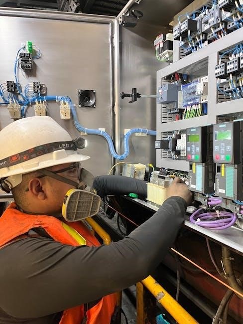
Safety is paramount when working with circuit breaker panels․ Always de-energize the system before starting tasks․ Use appropriate PPE, including insulated gloves and safety glasses, to prevent shocks and injuries․ Ensure all tools are rated for the voltage and current levels involved․ Following local electrical codes and manufacturer guidelines is crucial to avoid hazards and ensure compliance․
4․1 Essential Safety Tips for Working with Circuit Breaker Panels
Always de-energize the system before starting work․ Use insulated tools and PPE like gloves and safety glasses․ Verify power is off with a multimeter․ Follow the wiring diagram to avoid incorrect connections․ Ensure the panel is properly grounded․ Never work in damp conditions․ Adhere to local electrical codes and manufacturer instructions․ Keep the work area well-ventilated and clear of flammable materials to minimize hazards․
4․2 Personal Protective Equipment (PPE) Requirements
Essential PPE includes insulated gloves, safety glasses with a face shield, and arc-rated clothing․ Ensure all gear meets NFPA 70E standards․ Use a voltage-rated multimeter to confirm de-energization․ Wear steel-toe boots and non-conductive tools․ Regularly inspect PPE for damage or wear․ Never compromise on safety gear to prevent electrical shocks, arc flashes, or physical injuries while working with circuit breaker panels․

Common Types of Circuit Breaker Panels and Their Wiring Diagrams
Residential, commercial, and industrial panels vary in complexity․ Wiring diagrams for each type detail specific configurations, ensuring safe and efficient electrical connections tailored to their unique applications and requirements․
5․1 Residential Circuit Breaker Panels
Residential circuit breaker panels are designed for home electrical systems, providing a centralized control point for distributing power․ These panels typically include main breakers, branch circuits, and grounding systems․ Wiring diagrams for residential panels detail connections for outlets, lighting, and appliances, ensuring safe and efficient power distribution․ They often feature single-phase configurations and include clear labels for easy identification of each circuit’s purpose, adhering to local electrical codes for safety and reliability․
5․2 Commercial Circuit Breaker Panels
Commercial circuit breaker panels are designed for larger electrical systems, managing higher power demands in businesses and industrial settings․ These panels often feature three-phase configurations, multiple branch circuits, and advanced safety mechanisms․ Wiring diagrams for commercial panels detail complex connections, including main breakers, distribution channels, and grounding systems․ They ensure reliable power distribution, adhering to strict safety and efficiency standards for commercial operations․
5․3 Industrial Circuit Breaker Panels
Industrial circuit breaker panels are designed for heavy-duty applications, managing high-voltage systems and complex electrical demands․ These panels often include three-phase power distribution, motor control centers, and specialized circuit breakers․ Wiring diagrams for industrial panels detail intricate connections, ensuring safety, reliability, and efficiency in demanding environments․ They are crucial for maintaining uninterrupted power supply in industrial settings․
Step-by-Step Guide to Installing a Circuit Breaker Panel
Installing a circuit breaker panel involves preparing tools, mounting the panel, connecting wires to breakers, and testing the system․ Ensure safety and compliance with codes throughout the process․
6․1 Planning and Preparing for Installation
Plan the installation by assessing load requirements and selecting the right panel size․ Gather tools and materials, including the wiring diagram, to identify connections․ Ensure compliance with local codes and safety standards․ Verify the circuit breaker panel’s compatibility with existing systems and prepare the site for installation, ensuring power is off during work․
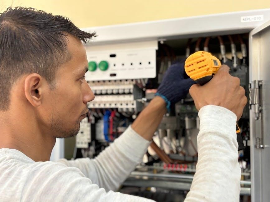
6․2 Mounting the Panel and Connecting Wires
Mount the circuit breaker panel securely on a wall, ensuring it’s level and accessible․ Connect the main feeder wires to the panel’s bus bars, referencing the wiring diagram for correct placement․ Attach each branch circuit wire to its designated breaker, ensuring proper connections and tightening all terminals․ Follow the diagram to connect neutral and ground wires safely․
6․3 Testing the Panel After Installation
After installing the circuit breaker panel, verify all connections using the wiring diagram․ Turn on the main power and test each breaker to ensure proper functionality․ Check for short circuits and overloaded conditions․ Use a multimeter to confirm voltage readings and ensure all safety features, like ground fault protection, are operational․ This step ensures the panel operates safely and efficiently․
Troubleshooting Common Issues in Circuit Breaker Panels
Troubleshooting involves identifying faults in the wiring diagram, resolving common tripping issues, and addressing overloaded circuits or short circuits․ Always refer to the panel’s wiring diagram for guidance․
7․1 Identifying Faults in the Wiring Diagram
Identifying faults in a wiring diagram involves checking for short circuits, overload conditions, or incorrect connections․ Use testing tools to verify circuit integrity and ensure all components are properly labeled․ Refer to the diagram to trace wiring paths and pinpoint issues efficiently, ensuring safe and effective troubleshooting of the circuit breaker panel․
7․2 Resolving Common Tripping Issues
Common tripping issues often result from overloaded circuits, short circuits, or ground faults․ Inspect wiring for damage or loose connections and ensure proper circuit breaker sizing․ Resetting the breaker after addressing the root cause can resolve most tripping issues․ Always switch off power before troubleshooting and use appropriate tools to ensure safe and effective solutions․
The Role of Circuit Breaker Panels in Electrical Systems
Circuit breaker panels serve as the central hub for electrical distribution, protecting against overcurrent and safely distributing power to various circuits․ They ensure reliable and efficient energy management․
8․1 Functionality of Circuit Breaker Panels
Circuit breaker panels act as central switches, protecting electrical systems from overcurrent and safely distributing power․ They enable manual or automatic disconnection of circuits, preventing damage․ Advanced panels offer smart monitoring, remote access, and energy-efficient solutions, ensuring reliable power distribution while adhering to safety standards for optimal performance and protection․
8․2 Integration with Other Electrical Components
Circuit breaker panels seamlessly integrate with components like RCDs, distribution boards, and smart devices․ This integration ensures safe and efficient power distribution, enhancing system reliability․ Proper connections with wiring diagrams guarantee compliance with safety standards; Modern panels also support energy management systems and smart home technologies, enabling remote monitoring and control for optimized performance and energy efficiency․
Legal and Regulatory Requirements for Circuit Breaker Panels
Circuit breaker panels must comply with local electrical codes and safety standards․ Certifications and adherence to regulations ensure safe and efficient installations, as detailed in wiring diagrams․
9․1 Compliance with Local Electrical Codes
Compliance with local electrical codes is crucial for circuit breaker panels; Wiring diagrams must adhere to regulations like NEC standards, ensuring safety and proper installations․ Certifications and inspections guarantee adherence, preventing hazards and legal issues․ Always verify local requirements before proceeding with any panel wiring or modifications․
9․2 Certifications and Standards for Circuit Breaker Panels
Circuit breaker panels must meet certifications like UL and IEC standards, ensuring safety and performance․ Compliance with NEC guidelines guarantees reliable installations․ Certifications verify components meet quality and safety benchmarks, protecting users from hazards․ Always ensure panels and wiring diagrams adhere to these standards for optimal functionality and regulatory compliance․
Advanced Features in Modern Circuit Breaker Panels
Modern circuit breaker panels integrate smart technology, offering features like remote monitoring and energy-efficient solutions․ These advanced systems enhance safety, optimize power consumption, and improve overall electrical system performance;
10․1 Smart Circuit Breakers and Remote Monitoring
Smart circuit breakers integrate advanced technology, enabling remote monitoring and control via smartphones or tablets․ These devices provide real-time updates on power usage, detect faults, and allow users to reset breakers without physical access․ This feature enhances convenience, reduces downtime, and ensures faster troubleshooting, making them ideal for modern electrical systems and smart homes․
10․2 Energy-Efficient Circuit Breaker Solutions
Energy-efficient circuit breakers incorporate advanced technologies like automatic voltage regulation and smart load management․ These solutions reduce energy waste and optimize power consumption․ By integrating with smart panels, they provide real-time energy monitoring and adaptive control, ensuring minimal power loss while maintaining system reliability and performance, making them ideal for eco-friendly electrical installations and modern energy-conscious designs․
Best Practices for Maintaining Circuit Breaker Panels
Regular inspections, cleaning, and testing ensure optimal performance․ Updating wiring diagrams and schedules prevents errors․ Always follow safety protocols and manufacturer guidelines for reliable and efficient maintenance․
11․1 Regular Inspection and Maintenance Schedule
Regular inspections of circuit breaker panels ensure safety and efficiency․ Schedule annual checks to identify wear, loose connections, and tripped breakers․ Clean components, verify wire integrity, and test circuit functionality․ Refer to wiring diagrams for accurate assessments․ Maintain detailed records of inspections and repairs to comply with safety standards and prevent potential hazards․
11․2 Upgrading and Replacing Circuit Breakers
Upgrading or replacing circuit breakers requires careful planning and adherence to wiring diagrams․ Ensure compatibility with existing panels and load requirements․ Disconnect power, remove outdated breakers, and install new ones following manufacturer guidelines․ Verify connections and test functionality post-installation․ Regular upgrades prevent overloading and ensure compliance with updated safety standards and energy efficiency regulations․
Tools and Materials Needed for Circuit Breaker Panel Wiring
Essential tools include wire strippers, multimeters, screwdrivers, and pliers․ Materials required are high-quality wires, connectors, circuit breakers, and mounting hardware to ensure safe and durable connections․
12․1 Essential Tools for Wiring and Testing
Key tools include wire strippers, multimeters, screwdrivers, and pliers for precise connections․ A circuit tester ensures proper wiring, while safety gear like gloves and goggles protects during work․ These tools are vital for accurate and safe circuit breaker panel installations and troubleshooting․
12․2 Recommended Materials for Safe and Durable Connections
Use high-quality wires with heat-resistant insulation and copper or aluminum conductors for reliability․ Flame-retardant materials and durable connectors ensure long-lasting performance․ Properly rated circuit breakers and busbars are essential for safe and efficient electrical systems․ These materials prevent overheating, short circuits, and potential hazards, ensuring durable connections and compliance with safety standards․
Common Mistakes to Avoid When Wiring a Circuit Breaker Panel
Common mistakes include improper connections, incorrect wire sizing, and ignoring safety protocols․ Always follow the wiring diagram and manufacturer guidelines to prevent short circuits and ensure compliance with electrical codes․
13․1 Avoiding Improper Connections and Short Circuits
Improper connections and short circuits are common issues that can lead to electrical hazards․ Ensure wires are securely connected to the correct terminals, avoiding loose or crossed connections․ Use the wiring diagram to verify proper circuit routing and load ratings․ Overloaded circuits and mismatched wire sizes can cause short circuits, so always follow manufacturer guidelines and test connections with a multimeter before powering up the system․
13․2 Ensuring Correct Wire Size and Rating
Using the correct wire size and rating is critical to prevent overheating and ensure safe electrical flow․ Always check the gauge and ampere rating of wires against the circuit breaker panel’s specifications․ Refer to the wiring diagram to confirm compatibility with the panel’s load requirements․ Proper sizing ensures efficient energy distribution and compliance with safety standards and local electrical codes․
The Future of Circuit Breaker Panel Technology
The future of circuit breaker panels lies in smart, energy-efficient solutions and remote monitoring systems, enhancing safety, reliability, and integration with modern electrical systems for optimal performance․
14․1 Emerging Trends in Circuit Breaker Technology
Emerging trends include smart circuit breakers with remote monitoring, energy-efficient designs, and integration with IoT devices․ These innovations enhance safety, optimize energy use, and enable real-time monitoring and predictive maintenance, reducing downtime and improving overall system reliability and performance in both residential and industrial settings․
14․2 Impact of Smart Homes on Circuit Breaker Panels
Smart homes are driving circuit breaker panels to integrate advanced features like remote monitoring, voice control, and energy management․ These panels now connect seamlessly with smart devices, enabling automated energy efficiency, real-time status updates, and enhanced safety through smart trip mechanisms, ensuring a more connected and responsive electrical system for modern living․
15․1 Summary of Key Points
A circuit breaker panel wiring diagram is crucial for understanding electrical systems, ensuring safe installations, and enabling efficient troubleshooting․ It provides a visual guide to components, connections, and safety protocols, complying with local codes and standards․ These diagrams are essential for maintaining reliability and ensuring the proper functioning of electrical systems in residential, commercial, and industrial settings․
15․2 Final Thoughts on Safe and Efficient Circuit Breaker Panel Wiring
Proper installation and adherence to wiring diagrams ensure safe and efficient electrical systems․ Regular inspections and maintenance are crucial to prevent hazards; Always follow local codes and use appropriate tools․ Understanding circuit breaker panels is key to reliable and hazard-free electrical operations, making them indispensable in modern electrical systems․